
I do think that the tolerance of the fft of ce18 is a bit big because although if you try to run the default timing samples of a 1khz you will get a reading of 1024hz.

Basic functions for displaying internal ROM fonts like a 16x4 LCD Extended function to fill the screen with a bitmap.
#ST7920 CODE EXAMPLE DRIVER#
I run the file and saw the followings in the watch window Ĭan someone please help me with this 2 problems asap. Simple driver for the ST7920 graphic LCD 128圆4. Is it because of my choosen of sampling freq, leading to bins resolution problem?Ģ. I then input the generate data in the data section of the ce18 project. In the freq domain, I have a peak freq of 4.69k. I generate a sine wave of 5k, Fsampling of 400k,


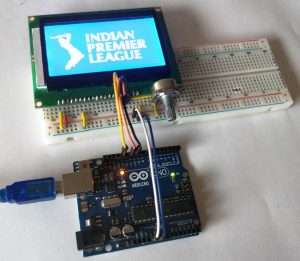
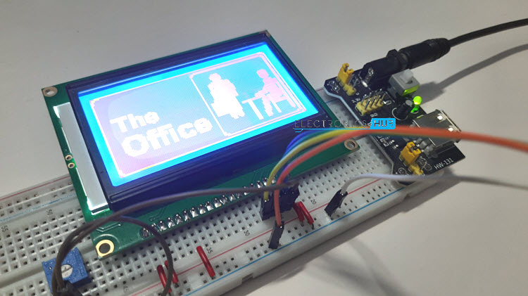
The line address starts from 0xb8 and goes till 0xbf as shown below. To select the lines we need to send the command/line address to GLCD. ERM12864SBS-6 is blue background with 128圆4 monochrome white pixels,ST7920 controller that is built-in with 8192 16X16 dots Chinese fonts and 126 16X8 dots half height alphanumerical fonts. For LCD only operations (text characters only) you can use the Great Cow BASIC LCD routines. Great Cow BASIC is currently supports 8-bit only. It supports 3 kinds of bus interface, namely 8-bit, 4-bit and serial. The required page can be selected using CS1,CS2 pins as shown below. ST7920 LCD controller/driver IC can display alphabets, numbers, Chinese fonts and self-defined characters. To conserve pins, only 4 data pins are used. The advantage of this controller is it can display Mandarin text apart from the Latin alphabets with only a few instructions to the display. One of the GLCD we are using in this tutorial is the ST7920-type controller. Lets view the GLCD as a open book with 2pages constisting of 8lines on each page.Įach line has 64 cursors positions to display data/images. To display graphics and text output from the PIC32, we need a Graphics LCD (GLCD). Connect D5 to the E pin you chose for the SPI bus, connect D7 to the R/W pin and RS to some GPIO pins on the ESP. Note that this component is for displays that are connected via the 3-Wire SPI bus. Negative voltage used along with Vcc for brightness control The st7920 display platform allows you to use ST7920 ( datasheet, electrodragon ) displays with ESPHome. Further the X-axis is divided into two parts of 64 pixels each and controlled by unique contoller/driver IC as shown in the above image.īelow table provides the detailed info of all the GLCD pins. Below image shows the internal block diagram of 128圆4 GLCD along with its pin out.Īs per the name it has 128pixels on X-axis and 64-pixels on Y-axis.


 0 kommentar(er)
